 |
|
||||||||||||||||||||||||||||||||||||||||||||||||||
 |
Flap-Flap (V2)
Servos, carbon fiber, and flapping wing
Presentation : Thierry Joubert
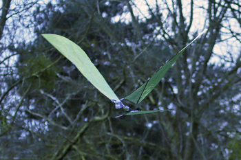
The Flap-Flap is an ultralight ornithopter powered solely by its servos. It is designed for experienced modelers wishing to explore flapping flight. This guide describes step-by-step the construction, assembly, and tuning of this flapping-wing model. Emphasis is placed on lightness, geometric precision, and electronic optimization. Patience, rigor, and perseverance will be key to bringing this demanding project to a successful flight.
Video illustrating the step-by-step
assembly of the Flap-Flap. |
| Video presentation of the Flap-Flap - ornithopter with flapping wings operated by servos. |
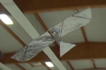
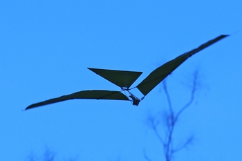
The Flap-Flap of the
German Stephan Brehm. |
 |
 |
|
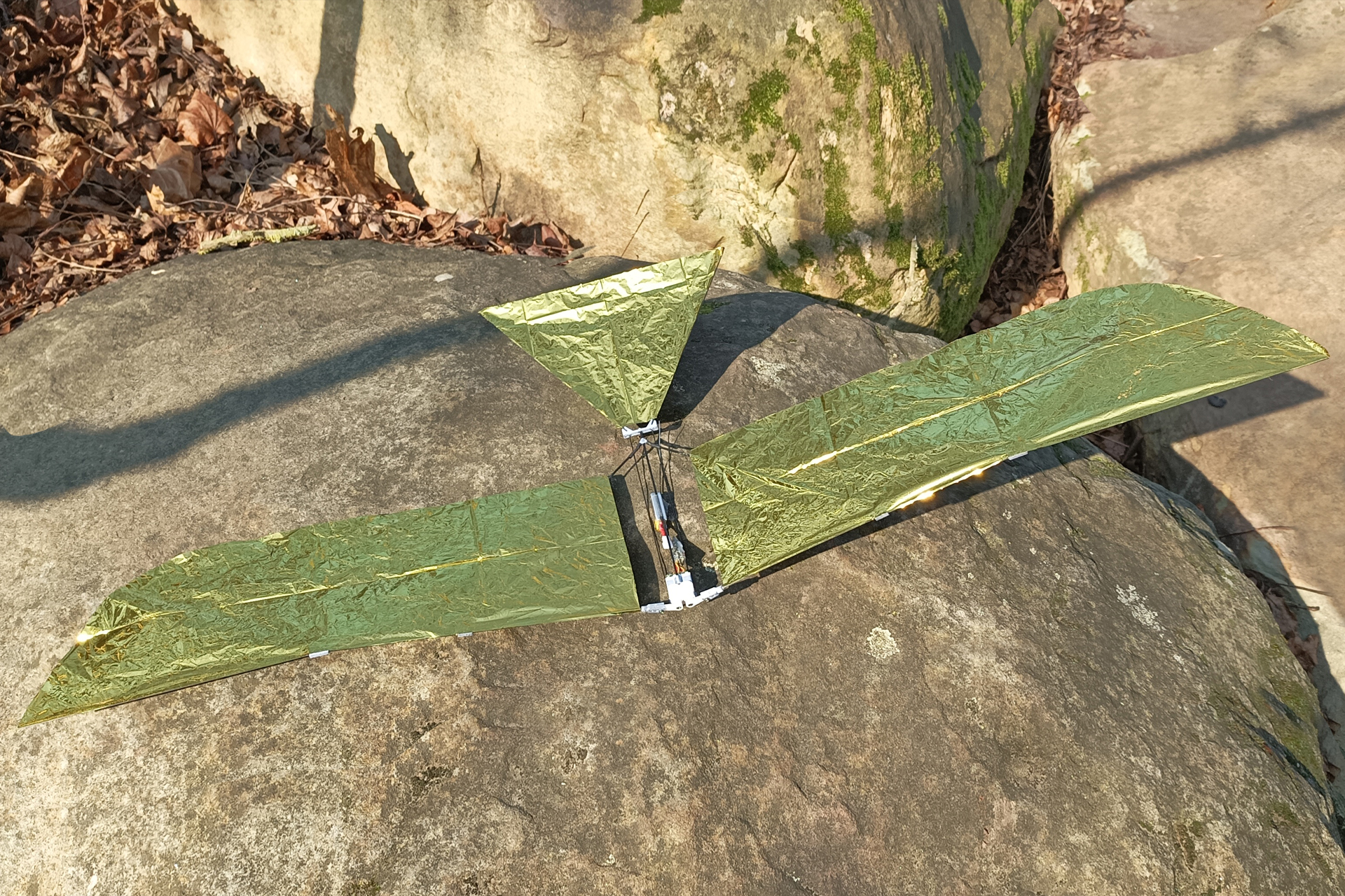
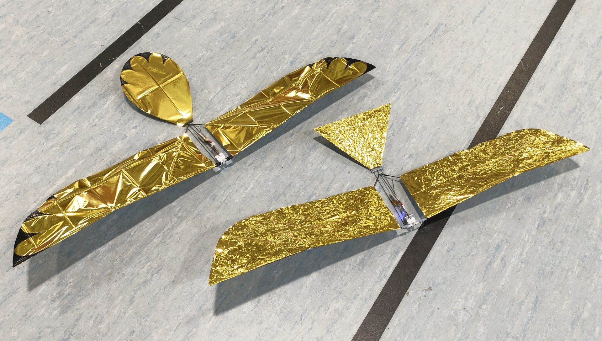
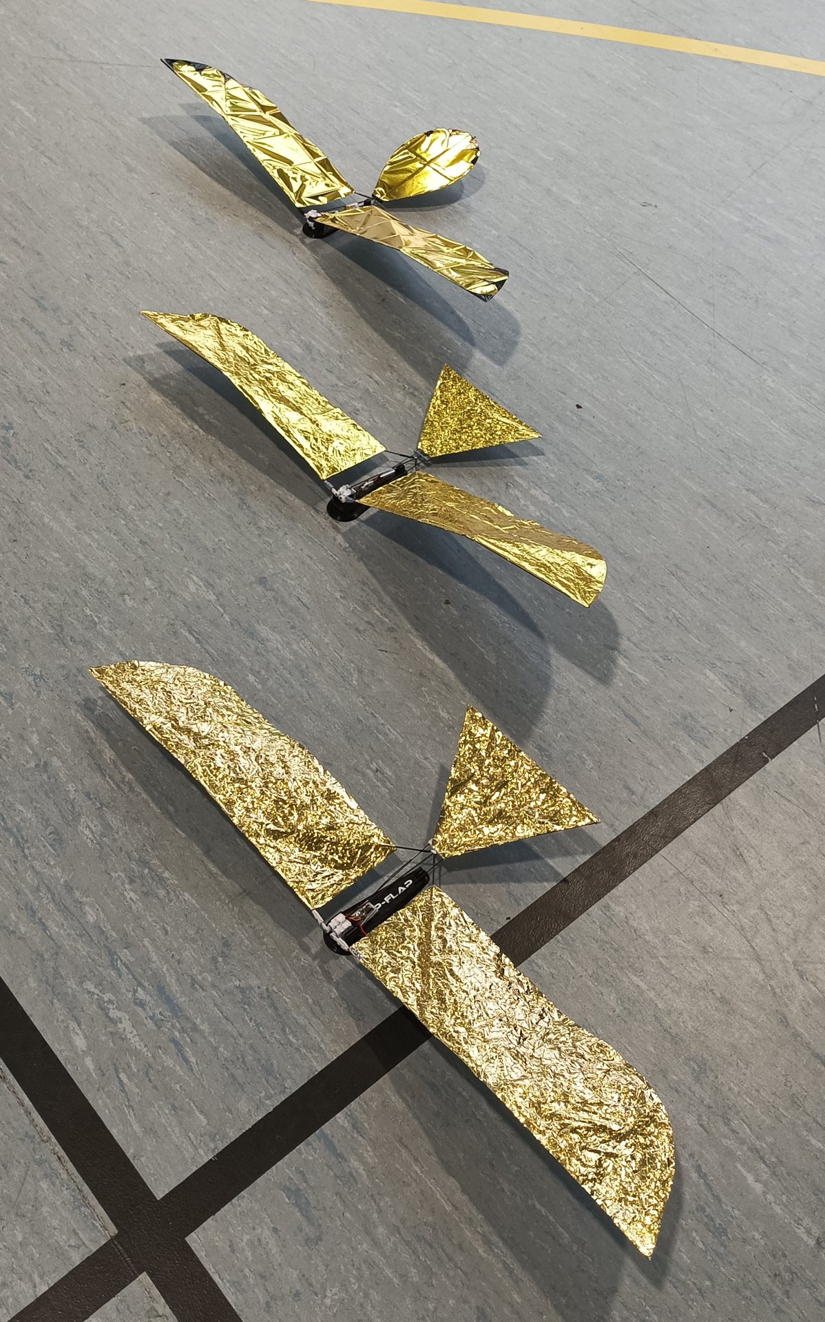
| The Flap-Flap is a minimalist flapping-wing aircraft. It features a simple airframe and electronics limited to two servos, a receiver, and a battery. The wings can be disassembled for transport. | ||
 |
 |
|
 |
 |
|
| The model weighs 23g ready to fly. It is perfect for flying indoors, or outdoors when there is absolutely no wind. | ||
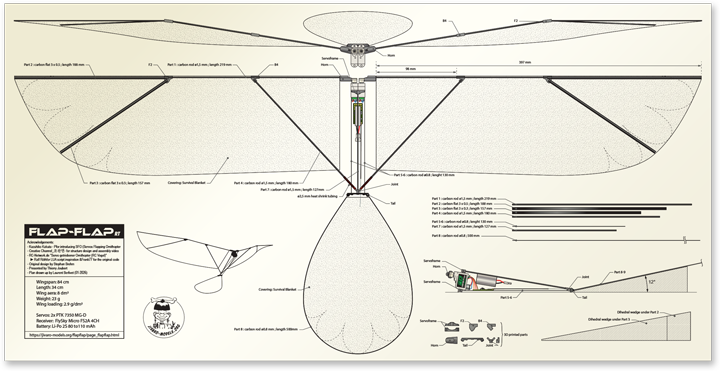
Technical specifications |
|
| Wingspan: 85 cm Length: 28,7 cm Surface area: 8 dm² Weight: 23 g Wing loading: 2,9 g/dm² |
Servos: 2x PTK 7350 MG-D Receiver: FlySky Micro FS2A 4CH Battery: Li-Po 2S 80 to 110 mAh Radio : OpenTx or EdgeTx accepting LUA Mix |
 |
 |
The purpose of this notice is to build from scratch a tiny lightweight ornithopter, driven and controlled just by two servos (SFO - Servo Flapping Ornithopter) and a LUA script in your Transmitter.
The targeted audience is experienced builders to experts:
- Thin Carbon structure
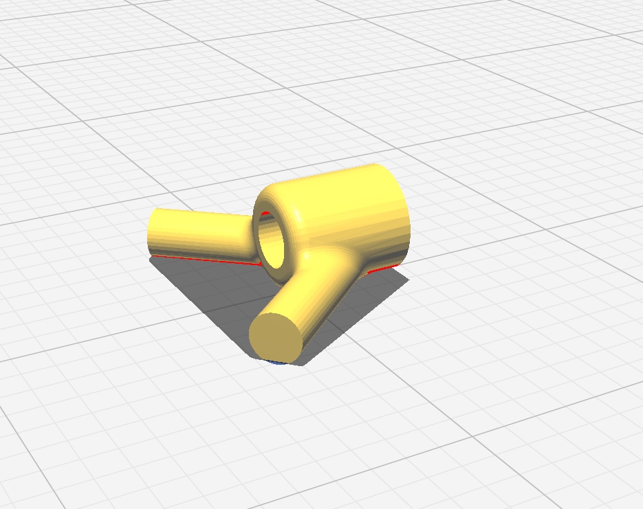
- 3D printed connectors
- Servo to RX soldering
- Power supply soldering and 1S LiPo assembly into 2S
- Target weight is challenging (less than 20g without the LiPo)
- Use good amount of frustration-tolerance and persistance to get it right...
Warning-1: Warning-2: |
 |
|
| Acknowledgements: • Kazuhiko Kakuta – for introducing SFO • Creative Channel_ • RC-Network.de “Servo getriebener Ornithopter (RC Vogel)” – Ralf Röth LUA script inspiration & Frank77 for the original code • Stephan Brehm – for super light version design… and guidance |
||
Bill Of Material |
|
Carbon *may be replaced by: |
 |
| Servos 2x micro-servos 5,5g |
 |
| Receiver 1x FlySky Micro Rx 1g |
 |
| Battery 10x Li-Po 3,7V 80 mAh |
 |
| Connectors 5x JST MX2.0 female connectors (2S elements) 2x JST MX2.0 male connector (Receiver and charger) |
 |
| Wings attachments 2.5 mm heat shrink tubing |
 |
| Wing cover 250 x 1000 mm Survival Blanket |
 |
| Glue Carbon & Connectors/servos Carbon & Survival blanket Servo & Servo |
 |
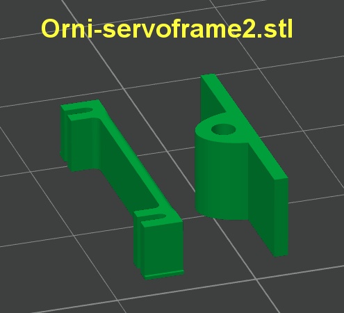
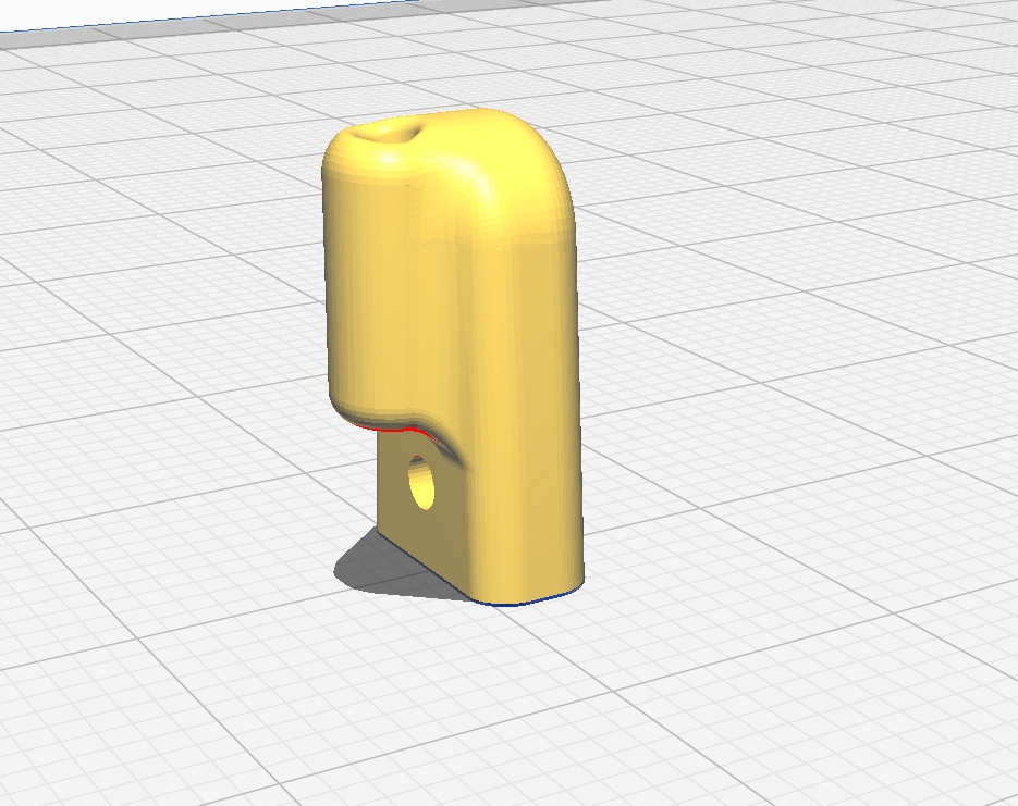
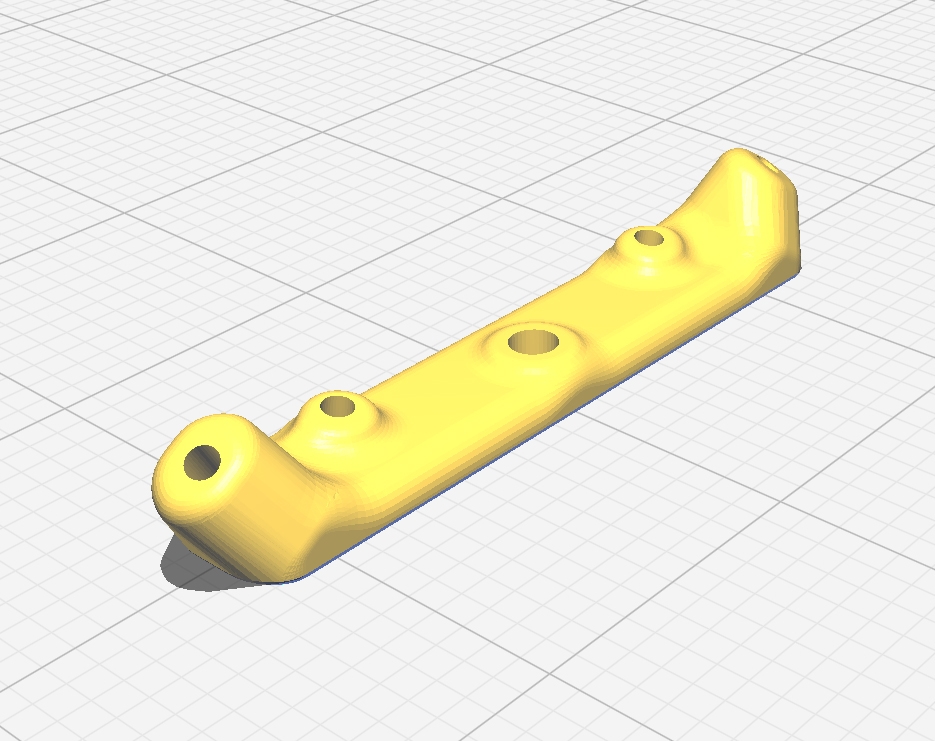
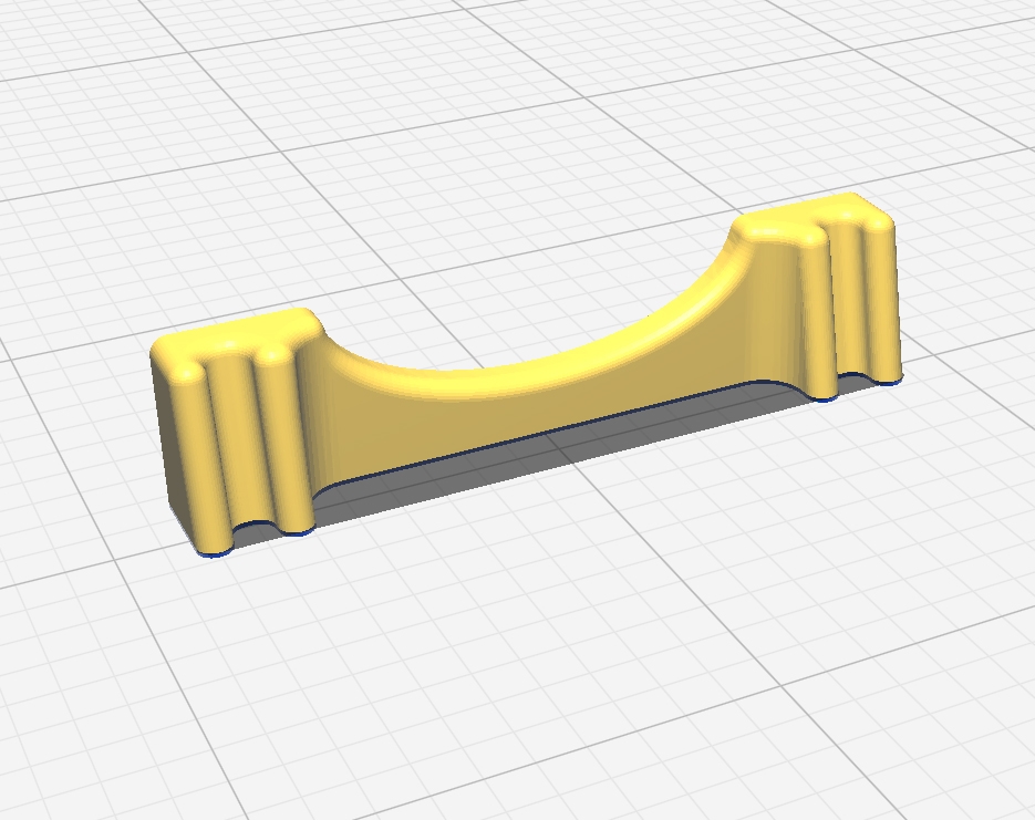
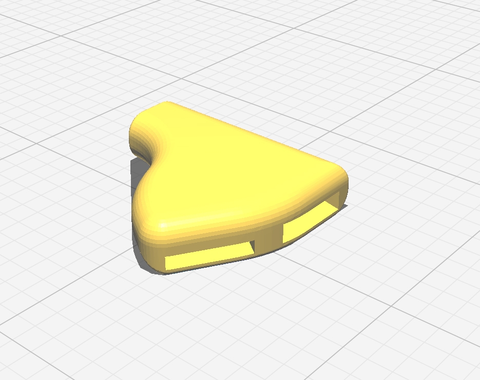
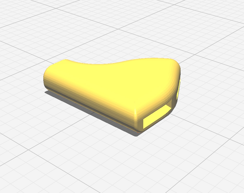
3D printing |
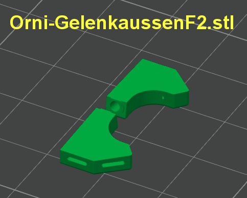
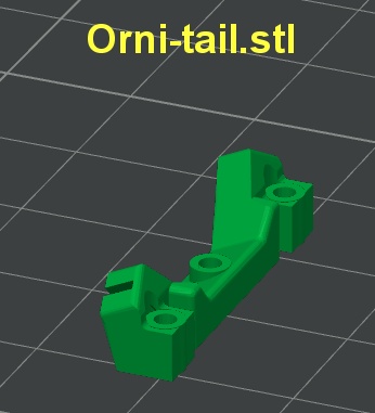
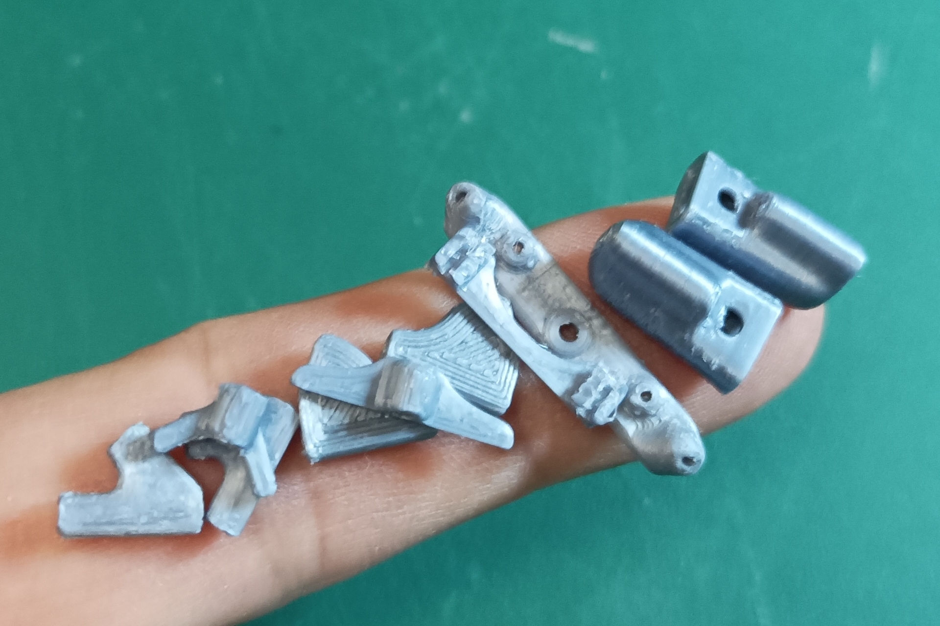
The necessary pieces are in six .STL files, some files
may contain extra parts that you don’t need to print.
![]() Choose
a tough 3D printing material (PLA+ is convenient).
Choose
a tough 3D printing material (PLA+ is convenient).
 |
 |
 |
 |
 |
 |
| The horns shown above on the left are reinforced parts! They are not the ones visible in the assembly photos below. The STL files for printing can be downloaded here (393 ko). | ||
|
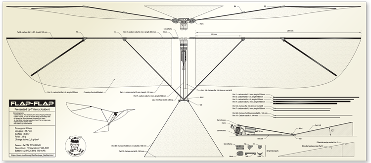
The Flap-Flap plan is
available for download in PDF format. |
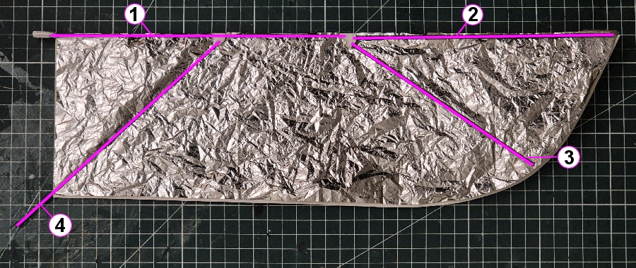
Preparing wing shape |
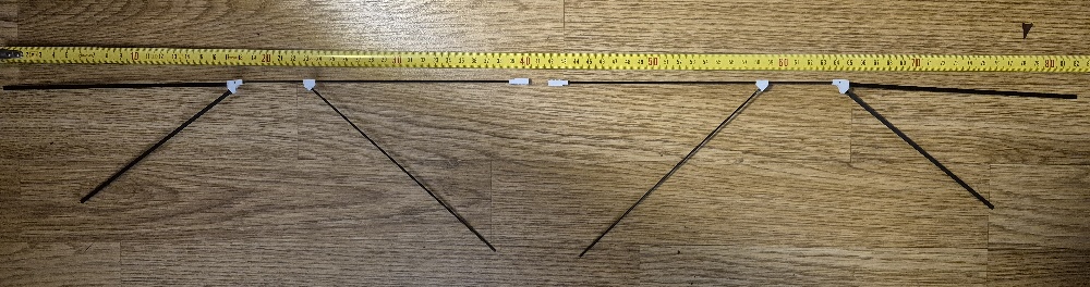
Here is the intrados of the Leftwing seen from below. Note that the wing is not flat - the tip part makes an angle towards the intrados:
 |
To prepare the wing shape, print the plan with a zoom factor of 100% on your printer or go to a blueprint printer. Make sure the dimensions are correct.
- Front (excluding "horn") = 397 mm
- Root = 115 mm
- Width at F2 connector = 120 mm
 |
If the dimension of your printed wing is not correct, adjust the zoom factor of your printer.
When correct, cut the shape of the wing to use it as a reference for future steps.
About grams |
The lighter your Flap-Flap will be, the better it will fly. Moreover the overall weight will have an impact on the required wing motion amplitude, and therefore on servos motors lifetime.
From the Bill of Materials, some weightsareimposed:
|
|
|
|
|
|
|
|
|
|
|
|
As a consequence the target weight of the carbon + 3D printed structure should be between 4 and 5 g.
|
 |
Assembling the wings |
 |
Left wing seen from below |
|
|
|
|
|
|
|
|
|
|
|
|
|
|
|
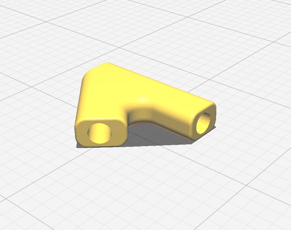
Each wing has three connectors:
|
 |
First glue the F2 connector to part #1 (1.5 mm rod)
|
 |
Then glue part #2 to the F2 connector, it should make a 11° vertical angle but no horizontal angle (#1 and #2 must make a straight line seen from above). This means an elevation of 35mm at the tip of part #2.
 |
 |
Glue part #3 to the F2 connector, it should make the same 11° vertical angle as part#2, this means an elevation of 30mm at the tip of part #3. For the horizontal angle you may follow the printed wing shape.
 |
B4 stays free to moveon Part #1 |
Glue part #4 to the B4 connector, but do not glue this connector to part #1 yet, just slide it as shown above.
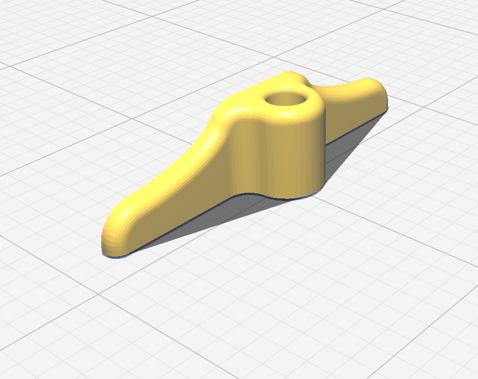
Glue the Servo Horn to part #1 taking care that it should be perfectly vertical from the surface of the wing.
|
 |
These horns may be attached to the servos nylon heads with screws to allow the unmounting of the wings for transport. |
 |
 |
After assembling, the
two wings should look like this. |
At this point the B2 connectors are slided in part #1 but not glued to it as their position will depend on the final body geometry
The attachment of each wing to the body will use two points:
Do not glue the B2 connector to part #1 yet, this will be done when the body is finished. |
 |
Assembling the body |
 |
The "fuselage"
and the tail assembly |
|
|
|
|
|
|
|
|
|
|
|
|
|
|
|
| *may be replaced by 0.7mm or 0.8mm rod | ||
The Body + Tail structure is made of 6 carbon struts, 4 connectors and the 2 servos PTK 7350 MG-D controlling the wings.
The 2 servos and their connectors will make the front of the body and it is glued to parts #5, #6 and #7. |
 |
Two connectors are at the rear of theBody:
|
 |
Servos and receiver |
The servos should be soldered to the receiver before gluing the carbon parts in place.
First remove the bottom part of the servos so that the motors are in contact with the air and can be cooled down. Add a small drop of hot glue to each motor so they do no slip out.
Then remove one sticker and assemble the two servos together using double sided thin adhesive tape (Check the geometry is perfect and press firmly).
Then you can glue the two connectors:
Always check that thealignment and the symmetry are perfect whenglueing |
 |
Cut the servo wires at about 25mm of the servos and solder them directly to the receiver. Right wing servo should go on Channel-1 and Left wingservo on Channel-2. The last soldering operation is the Power Line made with a MX2.0 male connector. The current required by the servos when flappinggoes up to 1.25 Amp and this is too much for the receiver circuit alone, this is why you should soldertwo copper bridges for Plus and Minus between the LiPo connector and the servos Plus and Minus(As shown in the picture). |
 |
Carbon structure of the body |
When the soldering is done, insert all carbon rods in place on the connectors, do not forget to slide Joint connectoron part #7. Remember that the Joint connector is NOT glued to part #7 Then you can glue all joins after checking that the geometry is perfect. The picture shows the overall shape of the body when it is finished. |
 |
Assembling the tail |
The last operation on the Body will be the tail assembly, two critical points:
- Follow the angle between the main part of the body and the horizontal surface of the tail.
- Be sure that the surface of the tail is perfectly horizontal
 |
The tail must make a 12° angle with parts #5 & #6. A practical solution for gluing the tail in place is to lay the body flat and use two 34mm blocks at the back corners of the tail.
 |
| > The triangle formed by rods #8, #9 and #10 can be made with a single hot-bent carbon rod. |
Finishing the wings |
When the body is ready, connect each Horn wing to its servo and connect part #4 to the Joint connector using shrink tubing (not yet shrunk).
Put the wing shape in place to check that the overall geometry is correct. Once both wings make a perfect line perpendicular to the body you have the correct place of each B2 connector, then you may keep the position with a piece of adhesive tape.
 |
Now carefully unmount the wings assuring that the B2 connectors stay in place.
Place each wing upside-down on a flat surface anf check that the tips of part #2 and part #3 are at the right distance of the surface:
- Tip of part #2 = 35mm
- Tip of part #3 = 30mm
You may use shims to keep the tips of part #2 and #3 at the right distances during the manipulations.
This operation is critical, you must be sure that the two wings have identical geometries. Experience has shown that if the angles of part #2 and part #3 are different between Left and Right wing, the Flap-Flap will naturally turn on one side.
> Now you can glue the B2 connectors to Part #1 of Right and Left Wing.
 |
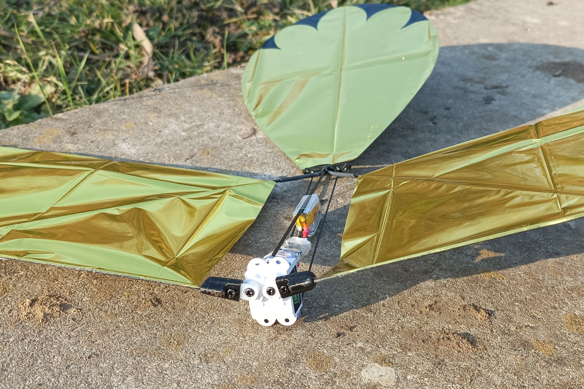
Minimalist frame, but
one that requires care. |
Using the wing shape, cut each Wing surface in the survival blanket. Then wrinkle it properly (3 times in your hand), and maintain it in place on the working surface.
 |
Cutting up the survival
blanket used as covering. |
You can then spray 3M super-77 glue on the extrados of the wing structure and apply the structure on the cover (you have about 30 seconds before it dries)
 |
Do the same with the tail surface, now you can assemble all pieces together.
Without the LiPo your Flap-Flap must be less than 20 grams or it won’t fly properly, lighter is better.
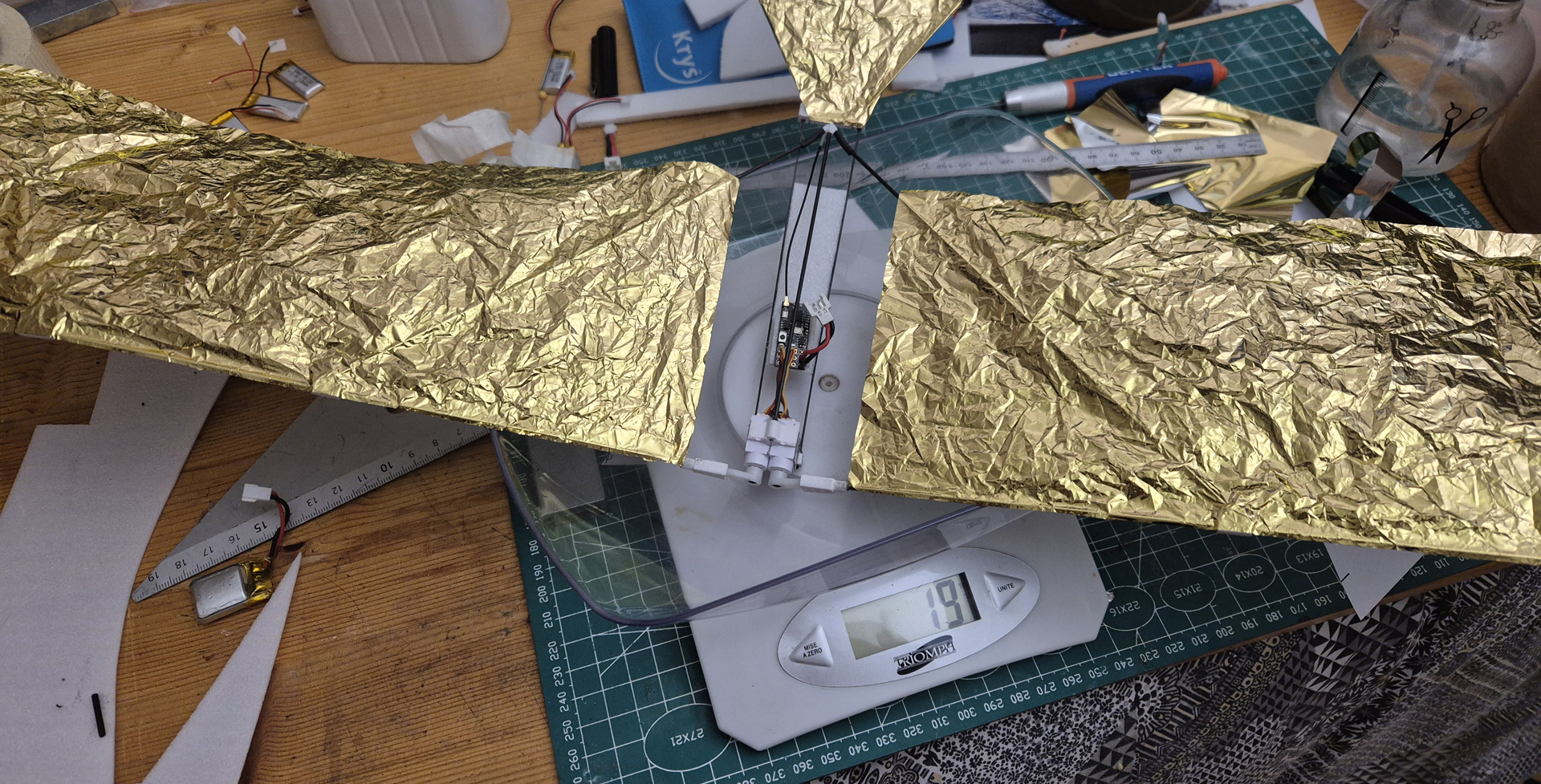 |
19g without the battery
is the target weight. We can still do a little better. |
It is now time to heat up the shrink tube, not too much if you want to make the wings removable for easier transport.
Assembling 2S LiPo |
If you do not find 2S LiPo of 3 to 4 grams on the market, you can assemble two 1S 80mAh to 110 mAh LiPo into a 2S element.
Warning |
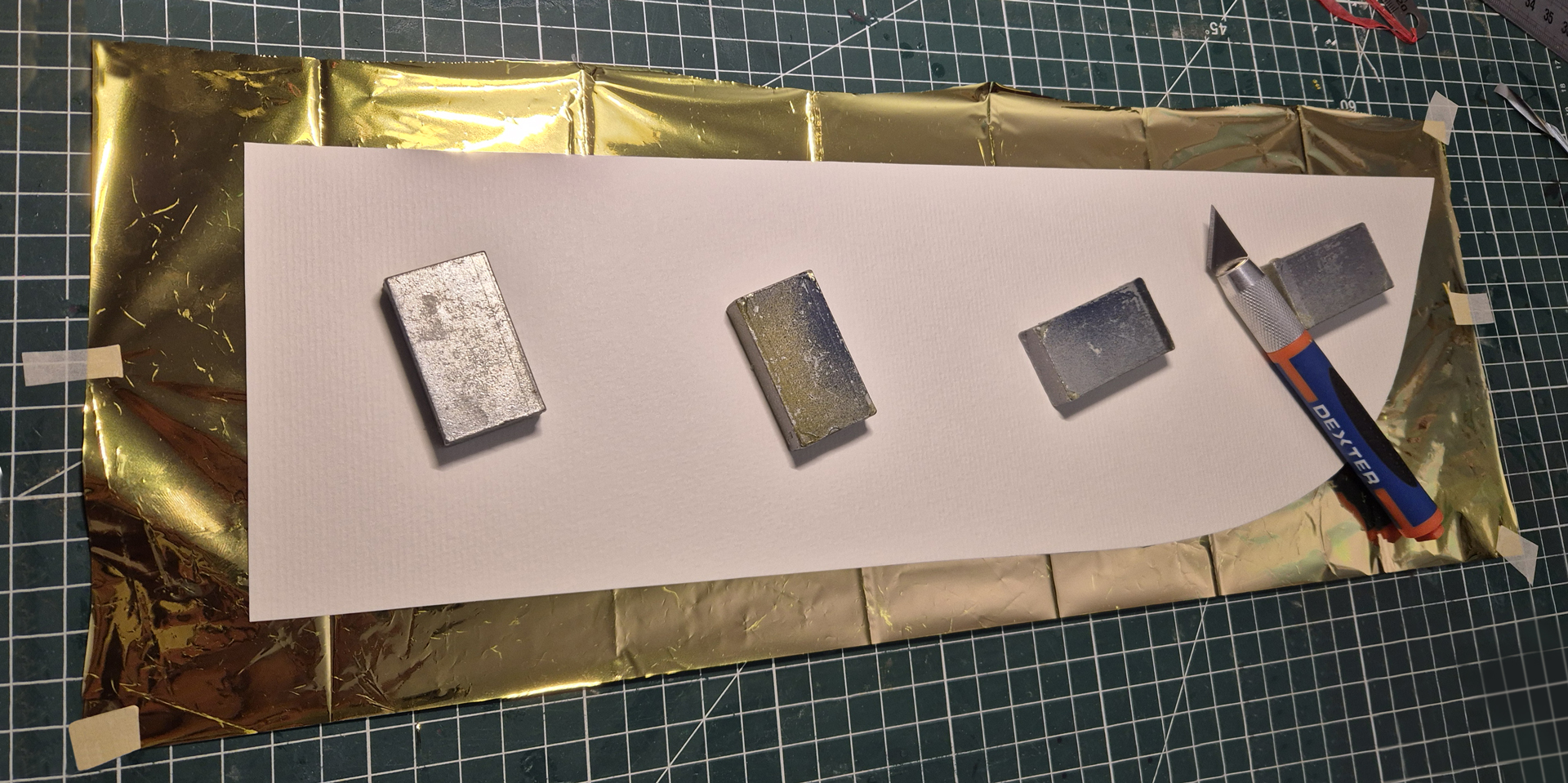
First remove the isolation adhesive yellow tape at the top of the 3.7V LiPo element. Remove the tiny electronic protection circuit in order to get the full current out of your battery (Flap-Flap requires 1.3 A peaks capability). This operation is delicate because the circuit
is welded to the LiPo flat connectors, avoid using a metallic tool
because you may short circuit the LiPo. You must leave enough connector to be able to solder the power wires. |
 |
For soldering the connectors without heating the LiPo you may use a freezing element that will cool it down as you heat up the connectors. Once the four connectors have been prepared with solder, note the Negative pole on each 3.7V element with a marker and put the two elements face to face in order to have the maximum spacing between the connectors. |
 |
Solder the black wire of a female MX2.0 connector to one Negative pole (don’t forget shrink tube for isolation), solder the red wire to the opposite pole on the facing LiPo (it MUST be Positive), then solder the two remaining connectors together as a bridge.
You have a super light 2S LiPo but without balance connector. Some chargers will handle the elements balancing, otherwise use a 1S charger on element 1 and 2 by connecting to the bridge (check polarity!) |
 |
Preparing the transmitter |
Copy the LUA script to the transmitter. Downloadable
file in the box below.
All pictures in this section were taken onan EdgeTXBoxer transmitter.
Instructions willapply for other EdgeTX/OpenTX transmitters but with different
graphics (LUA mix should work on Jeti as well, but this has not been tested).
Connect your transmitter with your computer via USB cable and choose USB Storage (SD) on the transmitter screen. A new volume ( i.e. D:) will appear on your File Explorer, copy the file SFO3.lua to the D:/SCRIPTS/MIXES folder, then diconnect the USB cable.
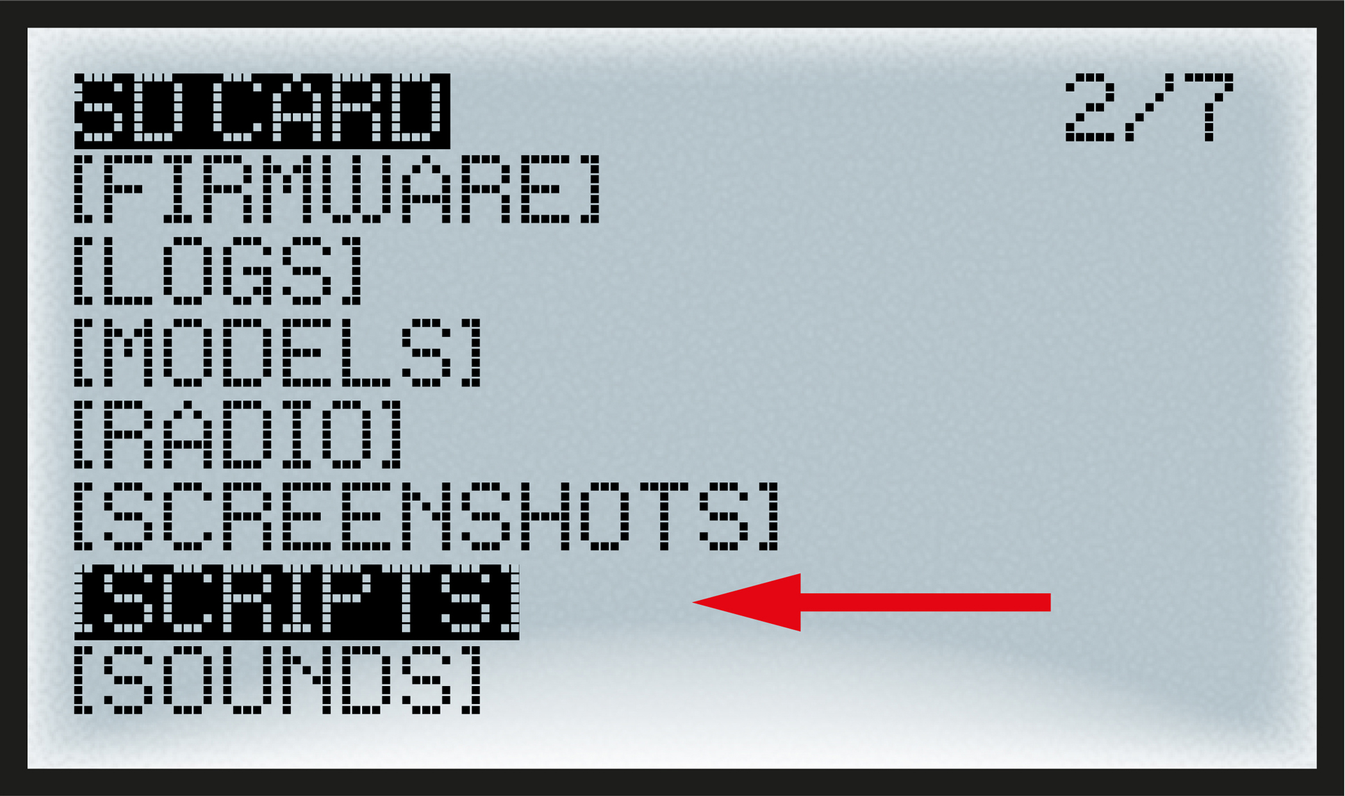
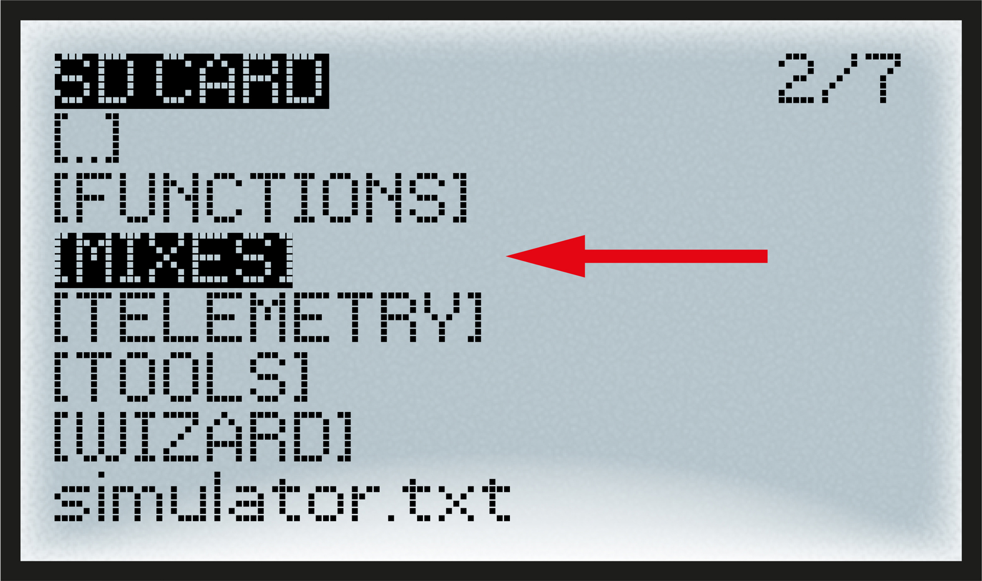
Open the transmitter main menu (not the models main menu). Go to the SD-CARD content page. There is a sub menu for SCRIPTS, open this sub menu. |
 |
There you find a folder called MIXES, open this sub menu. |
 |
You will see the SFO3.lua file (the SFO3.luac file will appear after activation) |
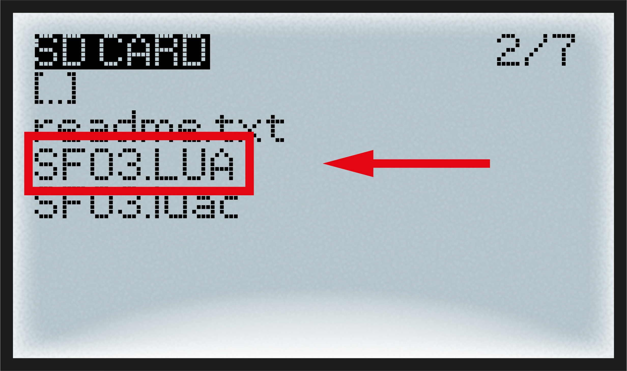 |
If you see something like that on your radio you are
succesfully done with storing the Lua script, leave the transmitter main
menu.
The rest takes place in the MODELS menu.
Set the model parameters |
Next step will be done in the MODELS main menu (not in the transmitter main menu). It requires that you already have created a basic model for your Flap- Flap there.
First we must activate the Flap-Flap Lua script and assign sticks to its inputs:
Open the MODEL main menu and select your Flap-Flap model. Go to CUSTOM SCRIPTS sub-page. Select LUA1 and in the Script section select SFO3 (it will be the only name to appear as you copied only one file to your SD-CARD). |
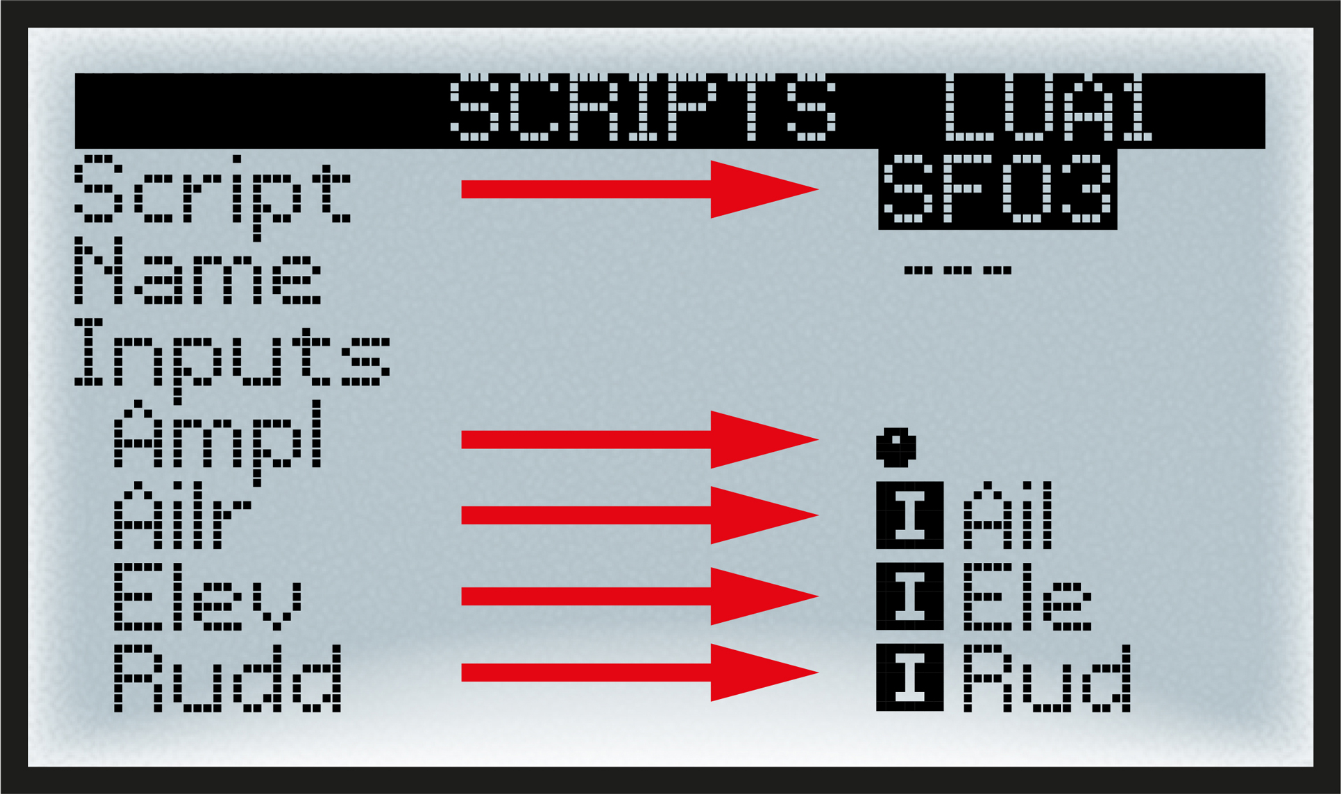 |
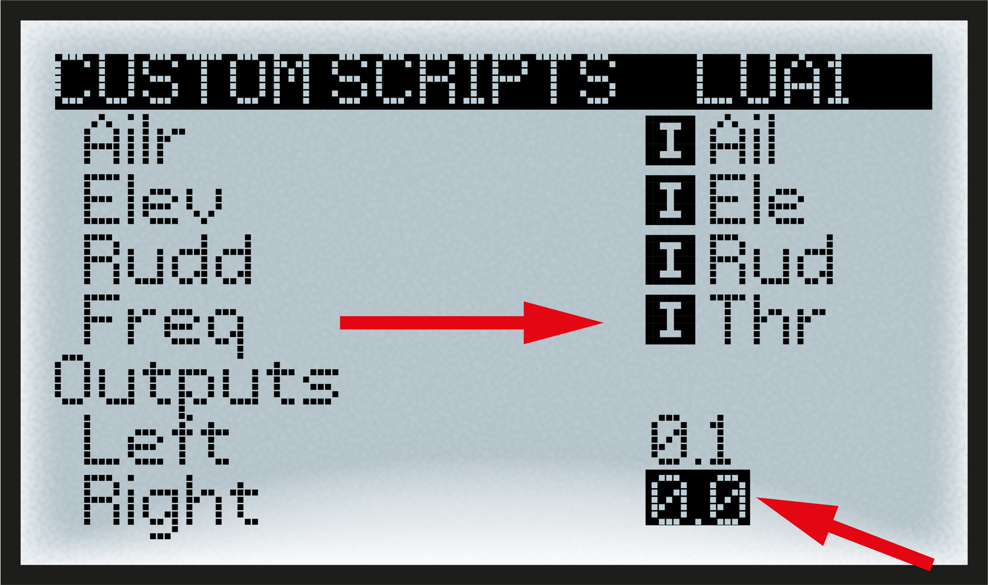
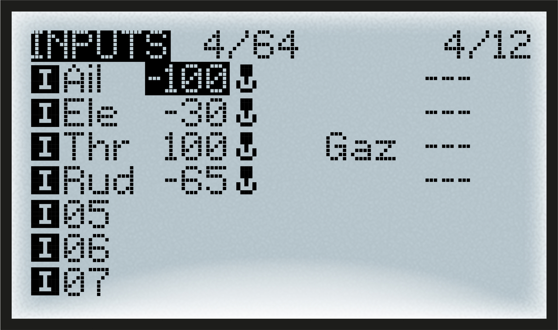
Navigate to the five input functions Ampl, Ailr, Elev, Rudd, Freq and assign for each function the related input stick or slider/knob. In the Custom Script screen you will see the outputs
Left and Right, their values should
change automatically if you push the Throttle. |
 |
Next step is to assign new Lua- outputs Left and Right as inputs for CH1 and CH2 where servos are connected.
In the MODEL main menu
go to MIXES sub page. Open CH2 and select Right as
source, add the same trims but reversed for Ele. |
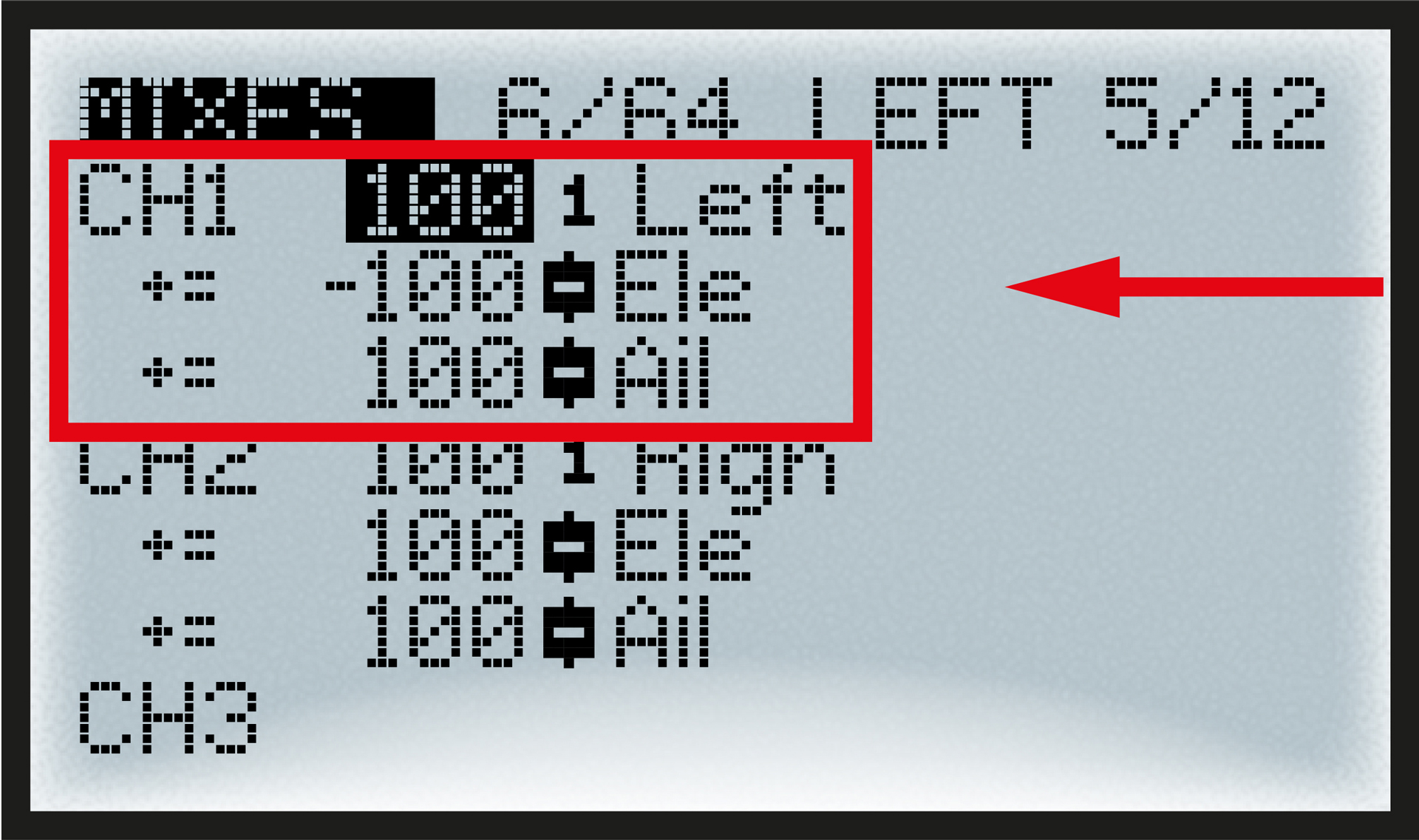 |
Trim-mixes for aileron and elevatorare useful to trim the bird during flight.Make sure to add only the trim function there, not the general stick.
From here when you bind your Flap-Flap receiver and move your sticks/slider both servos will act together. What remains is to programm weight of movements as you will do with any model.
TECH. CORNERThe LUA script will mix five functions to continuously calculate the motion of the two servos. These are Amplitude, Frequency, Aileron, Elevator and Rudder. My favorite is to set Frequency on Throttle and Amplitude on a slider/knob, but some pilots prefer the other way round Amplitude on Throttle and Frequency on slider/knob. Aileron and Elevator are working via changing the center-position of both servos. Rudder is working via changing the amplitude left/right. |
The first thing to check is the direction of your inputs, put your Flap-Flap on the ground and reduce the amplitude (to prevent the bird to jump around). Then manipulate each stick one at a time and control the motion:
- Ail
 Tail should bend in the direction of turn
 - Ele
Wings should go UP on push and DOWN on pull
- Thr
Wings should remain still on low, fast on full
- Rud
Reduces amplitude of inward wing (only when flapping)
The Ele axis of Flap-Flap is very efficient and you should reduce its weight or it will cause loopings. The Rud is also sensitive,you may reduce its weight. |
 |
Setting the right Ampl is a compromise because it has to be sufficient to keep Flap-Flap in the air but not too much to avoid burning the servo motors. Usually 50% of the slider/knob is a good choice, and always remember when flying to reduce the frequency to the minimum acceptable. Following these rules allowed to achieve 6 minutes flights.
 |
 |
|
If possible,
conduct the first flights indoors in order to properly adjust the
model and understand its behavior. |
||
Experience has shown that each Flap-Flap has its own personality, mine will fly better if the LiPo is attached (with adhesive tape) to part #7 right above the receiver.
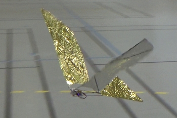
Pilot Flap-Flap |
 |
 |
|
 |
||
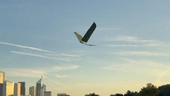
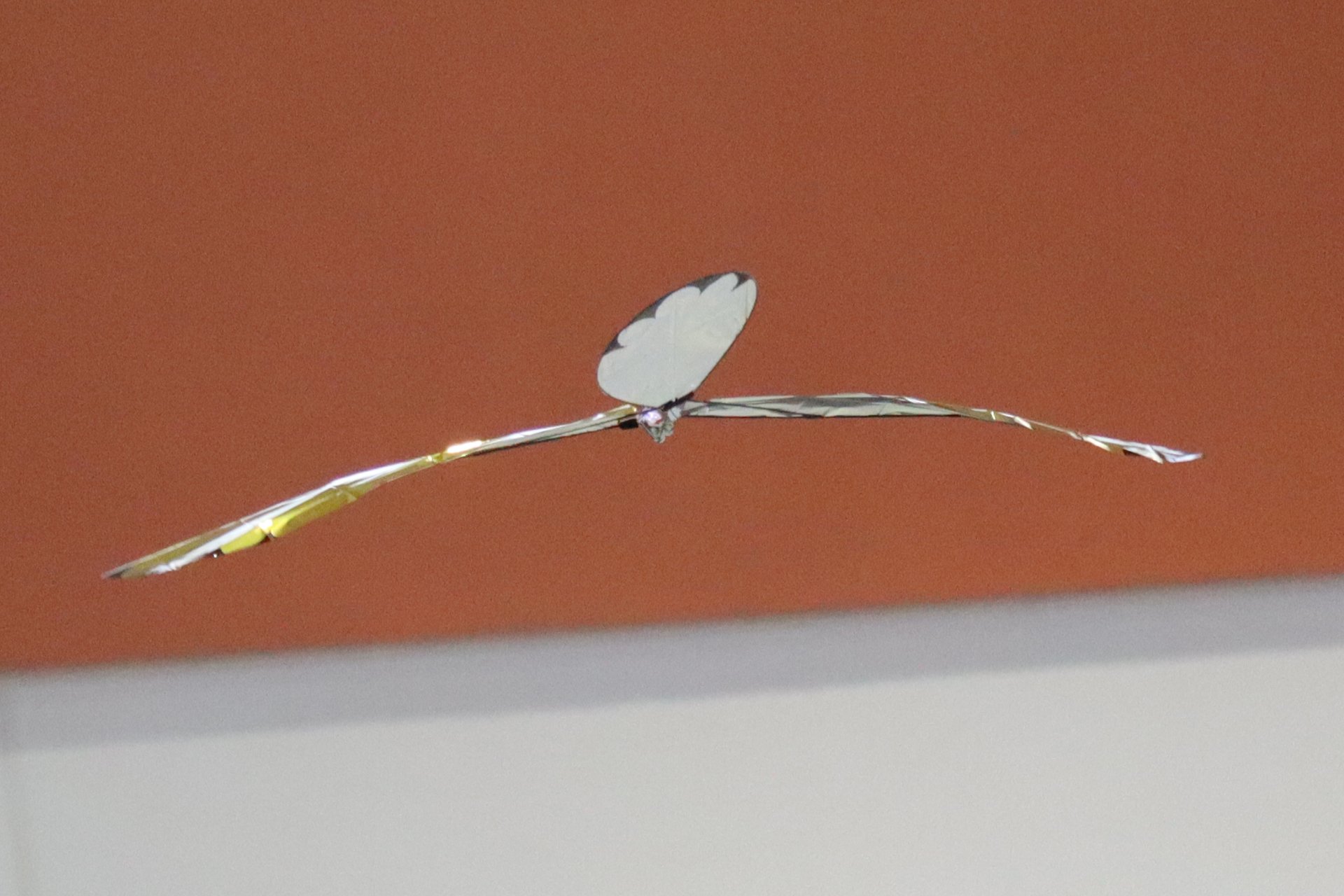
Flying the Flap-Flap
requires a bit of practice. You have to tame the bird... |
||
When you are skilled at flying an airplane, the assignment of flight controls as described in the previous chapter allows you to fly the Flap Flap without having to learn a new flying logic (unlike switching from a plane to a helicopter or a drone, for example).
 |
 |
However, even if you have all three axes on the sticks, the behavior of the craft in flight is closer to that of a two-axis plane; the ailerons don't really affect roll, so you have to 'stir the mayonnaise' to control the two axes of the Flap Flap:
- Level flight (pitching) is done with the elevator control just like an airplane that would be super sensitive to pitch.
- The turn (yaw & roll) is the result of a sequence rather than just a simple command to the ailerons; I will try to break it down below.
 |
 |
It is important to remember that it is mainly the tilt of the tail—resulting from the aileron control—that makes it turn; it somewhat plays the role of dihedral on a two-axis aircraft. The first condition, therefore, is to ensure that we have relative wind (we are moving forward or facing into the wind) before applying the ailerons.
 |
 |
The second condition for the tail to make a turn is its angle of attack in the relative wind. This angle of attack is negative by design and can be amplified if you make the Flap-Flap dive. So don't hesitate to push the elevator stick a little at the same time as you give the ailerons. Be careful, as soon as it starts to turn this way, the Flap-Flap quickly goes into a committed turn; the best way to get out is to bring the ailerons back to neutral and reduce the flapping.
 |
 |
The last element of the turn is the rudder control;
it generally cannot make the Flap-Flap turn on its own, but it provides
assistance on the yaw axis, which can prevent the committed turn described
above.
A successful turn will therefore require using all the controls at the
same time.
 |
ANNEX1 – Flap-Flap LUA ScriptUpdated March 17, 2026
The first SFO3.lua script provided for Flap-Flap is very simple, it calculates two extreme wings positions MIN and MAX and sends these to the servos with the correct timing. This script is very efficient and it has been used succesfully by all constructors since this notice was published. Still, this wings control mode I call "Min-Max" has some drawbacks:
To obtain a better control of the wings, a new calculation method was proposed by a member of my club in Colombes – Gérard – as a fine-grain control path calculated with a sinus function that makes the motion smoother.
The sinus flapping immediately proved its efficiency when the frequency is low, the motion is both realistic and better for the servos. However when the frequency goes high, as a consequence of the command period (the time between two orders to the servos) which is between 40ms and 60ms, the shape of the sinus cannot be followed. This results in a cahotic and inefficient behaviour of the wings when you push the throttle. To keep efficiency at full throttle I wrote the SINMM.lua script where low frequency "sinus" is associated with high frequency "Min-Max". The transition threshold is at about 20% throttle. As this script contains two distinctive flight modes, I added a new input called "Plus" which allows for fine control on the amplitude of the sinus mode. The "Plus" parameter is added in sinus mode to the global "Ampl" parameter. Flying SINMM.lua I also noticed my Flap-Flap better obeys the rudder orders when the freqency is low (sinus mode). The installation procedure and settings remain the same as for the previous version. Note that there is an additional input: "Plus" to be placed on a button as is the case for "Ampl". Enjoy! |


Flap-Flap|rt (Round Tail)By Par Laurent Berlivet (Updated February 12, 2026)
This version of the Flap-Flap differs very
slightly from the original. The main difference is its rounded tail.
Instead of a rod cut into three pieces and then glued back together,
a single 50 cm curved rod forms the tail, making it easier to work
with and more robust.
|
||||||||||||||||||||||||||||||||||||||||||


Contact the author: Thierry Joubert
 |
|
|
|||||||||||||||||||||||||||||||||||||||||||||||||