A few days later I picked up a big package at
the post office: It contained eight big sheets of Liteply, two
sheets of aircraft grade plywood of the same size, aluminum
landing gear, engine cowling, and a whole bunch of spruce strip
material.
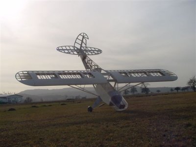
The ready to cover airframe is beautiful !
I would build a model like this again in a heartbeat ! |
First checks...
... in the shop back home: All the parts are cut out, except for
small tabs connecting the parts to the plywood sheets. Some of
the parts had to be picked up on the way between the car trunk
and the shop, because they had already fallen out of the sheets.
The strip material is of good quality as are the aluminum landing
gear, and the engine cowling made of heavy grade clear plastic
material. The “building instructions” consist of a
several DINA4 sheets, with a few drawings, two sheets of locator
plans for the individual plans, as well as two pages of text.
Here it becomes evident, that in order to successfully finish
this project, some previous experience building large wooden models
is required !
A small disappointment, when I saw the edges of some of the parts:
Due to either too high cutting speed or a dull router bit, the
edges were somewhat jagged. Thus the building of my Piper Super
Cub began with the removal and marking of all the parts from the
plywood sheets, and some cleaning up with sandpaper. This produced
a remarkable amount of parts, which promised a lot of building
fun !
As already mentioned earlier, the whole model is built up from
aircraft grade plywood and liteply. This requires the use of old-fashioned
wood glue, in order to achieve lasting strength in the structure.
I only used CA on non load carrying joints. Of course, the use
of slow setting wood glue requires an arsenal of pins, clamps
and strong masking tape.
Fuselage
Once I had all that in place I started on the fuselage: The two
large side panels are joined with the main frames, the lower fuselage
sheeting and the middle decks. This produces a central core, on
which the rest of the structure is based. Spruce longerons extend
the fuselage aft. Here a difference between the planning and material
selection showed up: The slots in the frames were cut for 7x5mm
longerons, however the supplied spruce material was 10x5mm, which
required some work on the frames. The basic fuselage build up
was done in a few evenings.
Tail
Next were the tail surfaces : This is the only area, where “composites”
are used: The tail surfaces consist of foam cores, which are sheeted
with 1.5mm plywood. Once sheeted, using a route, I cut out the
openings, to generate the looks of a built-up, open bay structure.
I then used a scroll saw to enlarge the bays even further, not
as much to save weight, than to make the appearance more scale.
The leading and trailing edges are made out of strips of liteply,
which then have to shaped to the airfoil contour.
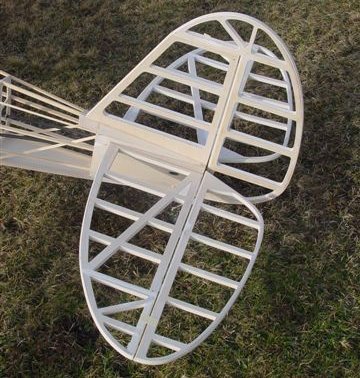
The tail surfaces consist of foam cores, sheeted with
1.5 mm plywood, which then are cut out to generate the
looks of a built-up, open bay structure. To improve the scale
appearance I enlarged the cutouts more than lined out in the
plans, also modified the counter surfaces on the elevators. |
Little change on the tail
The plans show all tail surfaces to be removable. However, I prefer
a fixed vertical stabilizer and rudder, with plug-in elevators,
so I modified the design: The horizontal stabilizer was divided
in three pieces. The two plug-in elevators, and an 8cm wide center
section, which was fixed to the fuselage permanently, together
with the vertical stabilizer and rudder. The elevators are attached
to the fuselage with two 6mm carbon rods, and secured with screws,
and of course, the flying wires.
Next are the wings
These are also built up entirely out of plywood and liteply, only
the leading edge is made of hard balsa. Something special is the
one-piece sheeting: the d-box sheeting, rib caps and trailing
edge sheeting are cut from one piece of 1.5mm plywood. The ribs
are made of Liteply, which look very delicate, but also are very
light. The spar is made of vertical Liteply strip, which has slots
for the ribs cut into it.
To begin the building of the wings, the lower sheeting is placed
on the plans. The main spar with is rib slots cut out, is used
as a template to mark the location of the ribs on the lower sheeting.
The spar then is the first thing to be glued to the sheeting.
Of course, when doing this, it is imperative to ensure that everything
is straight and square. Then the ribs are installed and weighed
down, while the glue sets. I installed four ribs at a time.
This procedure rewarded me with two beautiful wing halves, faster
than I had anticipated – two pieces of really nice woodwork!
What really surprised me, was the very small difference in weight
between the to wing panels of only 16g (0.56 oz), with one panel
weighing in at 1,645g (58 oz), the other one at 1,661 g (58.56
oz).
The wing joining system is unusual: It is made of two massive
beech wood dowels, which are glued into the three inboard ribs
of each wing panel, and engage in holes in the root rib on the
fuselage. All the holes in the ribs were undersized, which made
it necessary to painstakingly enlarge them until the dowels would
fit.
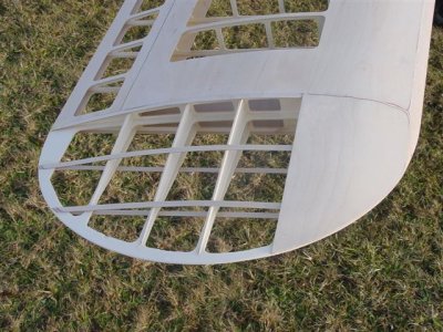
Wing tip detail. The wing tip is built up from 20
individual parts. |
Wing struts
The wing struts are fully functional, without them, the wings
will not hold on to the fuselage, even on the ground. The struts
are made of aluminum strip material, encased in pre-shaped spruce
strips. The building instructions include a drawing which shows
what pieces have to be cut from the aluminum for the struts. However,
the fact that on the original, the struts have different widths
caused some additional work, since the supplied pre-shaped spruce
material is of only one size, which required a lot of work with
plane and sandpaper to make the struts to scale. The attachment
fittings for the struts are also made from the aluminum strip
material. This work was performed by my club colleague Michael
Reiser. The fittings are then attached to the airframe with M3
bolts, the struts themselves are attached to the fittings on the
fuselage with M4 Allen head bolts. Once assembled, all this resulted
in a surprisingly tight ant stiff wing-fuselage joint the wings
have absolutely no movement relative to the fuselage.
Landing gear
The main landing gear was a piece of „heavy metal“!
It comes fully assembled, sprung and damped, ready to install.
Unfortunately, at 1,452 g (51 oz) it is also quite heavy. And
later on, I also noticed that it wasn’t exactly to scale,
being 16 mm (5/8 in) too wide. So, again I went to my club colleague
Michael Reiser, who reworked the landing gear to the correct dimensions,
and in the process also lightened it by 284 g (10 oz) !
The landing gear is attached to the fuselage by means of four
M5 bolts, which engage in blind nuts installed in the fuselage.
For wheels, I used the 140mm diameter units from FEMA (www.fema.de),
which are not only very scale in appearance, but also are ideal
for a model this size and weight, due to their design.
Detailing and improvements
Now having finished with the basic framework, it was time for
detailing and improvements. From the beginning, it was my goal,
no to just build “another Piper Cub”, but go new ways
when it came to painting and detailing. Of course for this, first
order of business was to locate a suitable full size Piper Cub,
on which to base my model’s appearance. There are still
hundreds of Super Cubs in active duty, some of them restored,
and maintained with lots of TLC, and others just being used as
workhorses. During my search, I came across the webpage www.airliners.net,
with a collection of nearly 500.00 airplane pictures. It was here
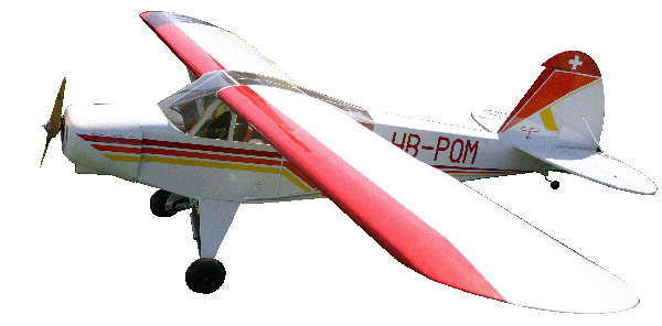
where I found the Piper Super Cub HB-PQM, based in the near of
Zurich (Switzerland), and I decided that this was to be the basis
for my scale Super Cub. Through the photographer, Jerome Zbinden,
I was able to establish contact with the owner of HB-PQM, Hansjörg
Huber. And so it was, that during a business trip to Zurich, I
was able to take measurements of the HB-PQM, as well as take lots
of pictures. During my stay in Zurich, Hansjörg Huber not
only supplied me with lots of additional info and pictures about
the Piper, but also a very nice lunch. We parted company with
the promise, to meet again and fly together, once that my model
would be ready.
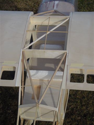
Beech wood dowels reproduce the welded steel tube
framing of the original, and are load carrying. |
Once back home, I immediately started to implement
all of the information gathered. First, the elevators: The models
layout has elevators with counter surfaces; the HB-PQM does not.
So I cut off the counter surfaces from the elevators, and glued
them to the horizontal stabilizer. Next, the cabin: The HB-PQM
is a military version, with the square windows, extending further
back than the round-cornered windows of the civilian version,
and it also has the big windows in the roof. Next came the cabin
interior: I decided to replicate the original’s steel tube
structure with wooden dowels. So, I created the structure piece
by piece, and removing in the original structure, as I progressed,
of course keeping an eye on structural integrity at all times.
Eventually, I replaced all the original structure with dowels,
except the two main frames. Maybe later...
Finally, I made a hat rack from balsa, two seats of Styrofoam,
and an instrument panel. The result was already quite appealing,
the “icing on the cake” so to speak. For the future
I plan on more detailing of the interior, installing instruments,
levers, etc.
Full assemble
Finally, in February, the big Piper could be assembled out side
for the first time, in its ready-to-cover stage. A really nice
and big airplane, with a weight of 9kg (19.8 lbs) right on target,
including wheels and landing gear.
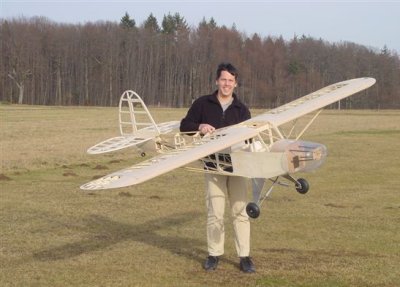
Unexpectedly assembling this all plywood/liteply
structure was lots of fun ! |
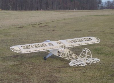
After eight months of building time, the model is
at the flying site for the first time. I am very satisfied
with the 9 kgs (19.8 lbs) empty weight. |
Here the weights of the individual
components:
Fuselage : 2600 g (91 oz)
Engine cowling : 490 g (17 oz)
Landing gear and wheels : 1650 g (58 oz)
Elevators : 490 g (17 oz)
Wings : 3340 g (117 oz)
Struts :430 g (15 oz) |
Finishing
After thoroughly cleaning up my workshop, it was time
to get started on the finish : Initially, I had planned on using
regular iron-on fabric, however, this idea was quickly dismissed
once I calculated the weight. Next option was AMZ-fabric, a very
tough, paper-like material, which would have to be installed the
old fashioned way using dope. This idea was also discarded, because
of time constraints, and also to avoid problems with the neighbors.
So, in the end, I decided on the proven “Orastick”
covering, made by Oracover (www.oracover.de).
Base color was to be “scale white”, of which 12m (
13 yd ) were required. For the color stripes, I sent a picture
of the HB-PQM to Ines Lanitz, the owner of “Oracover”,
who then sent me the covering in the correct colors.
The rest was routine: Cut the covering to size, clean the airframe,
iron the covering on, and then tighten it with the heat gun. After
one complete weekend, as well as several evenings spent on this
activity, the Piper was ready for installation of the drive train
and radio gear.
Equipement
Eduard Seidl’s recommendation for servos was to use high
quality units with at least 9 kg power. I decided on the HS-645MG
from Hitec. Theses servos weigh 55g (2oz), and have 96 Ncm (135
oz) torque on five cells, and are known for their robust gear
train and electronics. As receiver, I used the “DSQ-12”
from ACT (www.acteurope.de),
which apart from its 12 servo connections also has circuitry incorporated,
which directs the current directly to the servos, instead of routing
it through the receiver’s printed circuit board. A “DPSI-Powersystem”,
as the one I used on my Ju-52/3M, appeared to me as “overkill”.
Two five-cell 1300mAh receiver batteries and a „Safety Power
Switch AW15 DSQ" – also from ACT – completed
the radio gear installation.
Due to the ample space in the fuselage, the installation of all
these components took little time; most of the time was spent
on numerous soldering joints.
Hinge material for the control surfaces was included in Eduard
Seidl’s kit. The control horns, bowden type push-pull rods,
clevises, etc, were acquired from large scale expert Rainer Pfister
(www.fliegerlandshop.de/).
For the elevators, I selected the black/yellow bowden type push-pull
rods from Sullivan. As far as I know, these are the only ones
strong enough, and available in the length I required (130 cm).
I have already used these once, on my Ju-52/3M. For the rudder,
I used a pull-pull system, with plastic covered steel wiring.
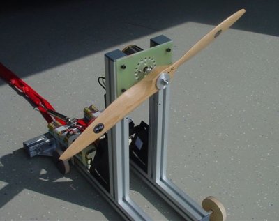
The motor test runs at the Torcman facility in Blaustein
on April 17th provided valuable information. |
Engine
After four weeks of mechanics, the last step to completion, April
17. With the almost ready to fly Piper in the car, I drive to
the village of Blaustein, near to Ulm in South Germany, to visit
Klaus Kraft, the owner of the company Torcman (www.torcman.de),
to pick up the Torcman motor built specifically for this model.
The idea was to receive the motor, and do some run-ups with it,
to assure power output and reliability. So, the motor is installed
on the test stand, and the controller and two 30cell RC-2400 packs
are hooked up. Propeller is a Flytec 26x10” wooden unit.
These propellers are known for their good efficiency and perfect
balance. Once on the test stand, Klaus Kraft slowly applied power.
The motor started smoothly, and he slowly increased power, until
the drive train was running at full power, showing some impressive
numbers: The 26x10” prop was running at 5,100 rpm, on 2.1
kW! During this, the double power pack was supplying 70 amps at
30.5 volts; and after two minutes run time, the test stand was
showing 9.6 kg (21 lbs) of thrust! After six minutes runtime at
different power settings, the power packs were depleted, everything
was shut down, and both of us took a deep breath! We did not expect
this much power, also the whole setup promised to be very reliable,
since after the test run, the motor was only at 70 deg C (158
deg F), and the controller at 55 deg C (131 deg F). So I had no
second thoughts when installing the drive train temporarily in
the model. Once installed, another test run was performed, and
it confirmed this, the drive was running smoothly, without vibrations,
and also, the heat buildup under the cowling remained in an acceptable
range.
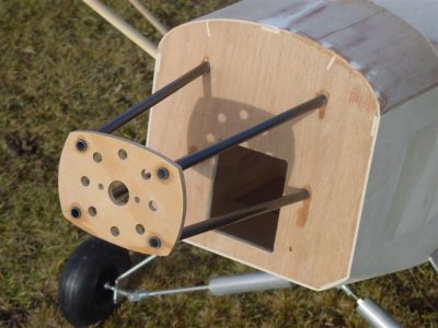
The motor mount for the Torcman TM 685 „monster“
motor. Four 10mm carbon rods maintain the distance of 230
mm from the firewall. Later on it is reinforced with diagonal
spruce strips, in order to increase stiffness. |
I now installed the drive train permanently
in the model. The motor, of course is attached to its motor mount.
The controller is placed directly below the motor, immediately
aft of the cooling opening in the cowling. For the two power packs,
a battery tray was made of 4mm plywood, and installed in the location,
where the fuel tank was supposed to be. The power packs can be
removed and installed through a big access panel on the side of
the fuselage. There is enough space in the fuselage, to get both
hands inside, in order to make the necessary connections. With
the power packs moved as far forward as possible, the CG was in
the correct location.
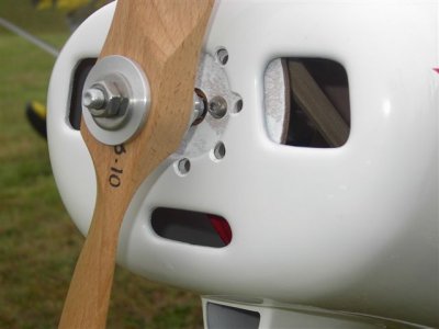
The motor is completely hidden under the big cowling.
The cooling holes in the front were necessary for adequate
cooling. |
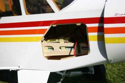
The side door allow acces for the 2 cells packs. |
Let's fly!
After a thorough range check, and another short run-up, it was
time: I set the flaps to their take-off position at ten degrees,
and apply power. At 20 per cent power, the big Piper starts moving
down the runway and is easily kept on track with the rudder. Once
full power was applied, it took no more than 20 m (60 ft) to become
airborne, and climb out with a 30 deg nose up attitude! Everything
felt right from the beginning. The model was responsive, but not
too much so, and followed the command inputs exactly. Once it
had reached a safe altitude, I throttled back to approx. 50 per
cent power, and flew a few big circles around the field. A very
scale like appearance !
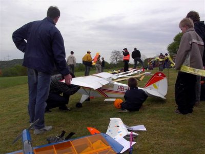
Ground handling is easy and fun. However, an assistant
is required when installing the wings and struts. |
Control surface
deflections :
Elevator : +/- 25 mm (1in)
Rudder : r/l 65 mm (2.55in)
Aileron s: + 15/-25 mm (+0.6in/-1in)
Flaps : +10°/+70° |
I immediately felt comfortable with the model,
as it flew very smoothly, but still very responsive. And the sound
of the big wooden prop was quite close to the sound of the original.
Also, the model’s air speed made it look very real, and
scale like. Five minutes later, the power packs were nearing the
end of their charge, and I set 70 deg flaps for the landing, which
was uneventful, almost routine.
Everything Okay! So, a little victory dances put an end to the
successful maiden flight. Motor, controller, and battery packs
were just warm to the touch.
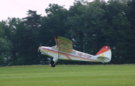
The Torcman-Monster motor pulls the big Piper in to
the sky with impressive power. |
The second flight this day was supposed to confirm
the findings of the first flight, but something happened: The
take-off was even a little more powerful than the first, with
the drive batteries delivering their full power, but during the
climb out, a few seconds after liftoff, the motor suddenly quit!
Overload of the controller? Shouldn’t, couldn’t be!
I pushed the big Piper nose down, and let her gain some airspeed,
and retarded the throttle. I then decided to try again, pushed
the throttle stick forward, and to my surprise, the motor came
back to life! I pulled the Piper around in a shallow turn, to
get back to the runway, only to have the motor quit again, this
time for good. And was forced to land the Piper in the field adjacent
to our flying site. To my great relief, once I got to the model,
I saw that it had survived the rough landing without any damage,
and had come to rest just a few feet away from a drainage ditch!
I don’t want to think about what could have happened...
But why had the motor suddenly quit? A quick check revealed the
problem: It wasn’t the motor or controller, but one of the
three 4mm gold-plated connectors between controller and motor,
which had come loose. So, it wasn’t a component failure,
but “human error”, I should have secured the connections
with some shrink tube. Which I have by now, this won’t happen
to me again!
Many successful flights followed. With the two 30 cell packs,
I achieve flights of up to ten minutes, with a sedate flying style,
in calm weather. If the weather is not as calm, or my flight style
is a bit more to show off, flight times will be between six and
seven minutes.
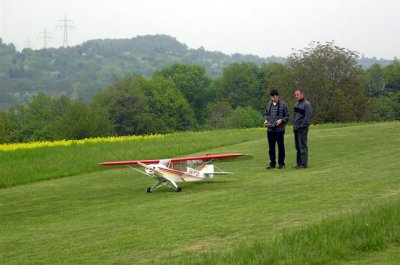
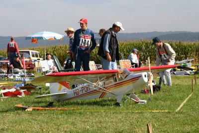
The model’s first public appearance at electro-meet
in Dietlingen near Pforzheim, May 1st. My friend Michael Gerst
assisted me during the flight on the very small airfield. |
I flew the Piper at the electro meet in Dietlingen
near Pforzheim on May 1st, as well as in Traunreut near Lake Chiemsee,
and at the TUN test flight weekend (see www.tun.ch
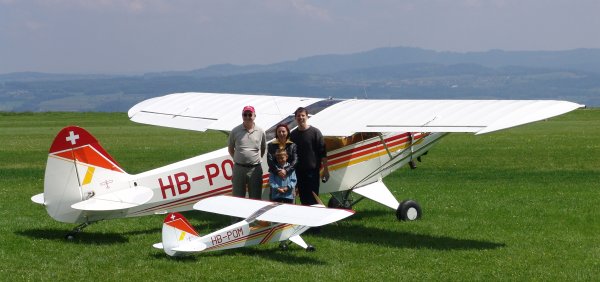
and AUFWIND 5/2004) in Switzerland. Here it was where I had my
very personal high light: Hansjörg Huber flew in from Zurich
with the full-size HB-PQM, and both airplanes posed next to each
other for the photographers. Of course I had to show off my model
in flight for him, and he, very graciously, invited me to a sightseeing
flight around the Zurichsee in the HB-PQM.
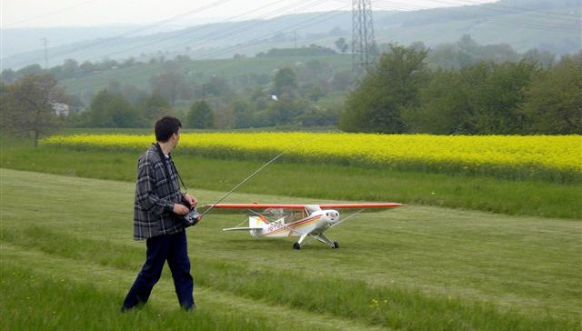
Ready for take off at the TUN test flight weekend
in Buttwil, Switzerland. |
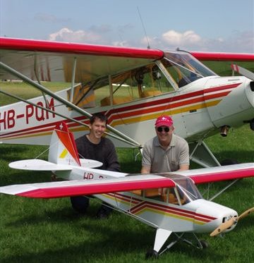
The flight in the original Piper with Hansjörg
Huber was a personal high note. |
This meeting gave me the opportunity to take
some more notes on details, which I plan to incorporate in the
Piper over time. Also, I finally was able to find a 1:3 pilot
figure. Simon Cocker recommended AH Designs from England: Their
1/3 scale pilot figure looks very nice, and weighs only 88g (3.2
oz).
Finally I can say: The HB-PQM is my model for
the new season. The plywood construction makes the model very
robust and able to handle the wear and tear of frequent use. Due
to the tough plywood sheeting, nicks, dings and scratches are
not much of an issue. Ground handling also is a joy. Just the
„loading“ of the model with two 30 cell packs is a
show all by itself!
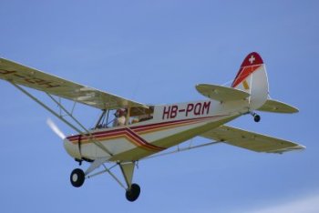
| The real plane, witch the model is based
on, flying over the Aspach airfield. |
Fact
Box
Designer
: Eduard Seidl
Distributor : MMB-Müller
Modellbau
Wing span : 3.600 mm (141 in)
Length : 2.300 mm (90 in)_
Flying weight : 18.100 g (39.9 lbs)
Motor : TM 685/30 14pole 18turns by Torcman
Controller : "Master MAX", Hacker
Drive battery : 60x Sanyo RC-2400, in 2 30 cell packs
Propeller : Flytec 26"x10", wood
Current : 70.5 A
Flight time : 8 minutes |
|
